 Loading... Please wait...
Categories
Popular Brands
Our Newsletter
- Home
- X10 Transmission Theory
X10 Transmission Theory
by Marmitek
Marmitek X-10 transmissions are synchronized to the zero crossing point of the AC power line. The design goal should be to transmit as close to the zero crossing point as possible but certainly within 200 microseconds of the zero crossing point. The PSC04 and PSC05 provide a 50Hz. square wave with a max. delay of 100 micro seconds from the zero crossing point of the AC power line. The maximum delay between signal envelope input and 120KHz. output bursts is 50 micro seconds.
A Binary 1 is represented by a 1 millisecond burst of 120 KHz. at the zero crossing point and a Binary 0 by the absence of 120 KHz. The XM10 modulate its input(fromthe OEM) with 120KHz., therefore only the 1 ms "envelope" need be applied to their inputs. These 1 millisecond bursts should actually be transmitted three times to coincide with the zero crossing points of all three phases in a three phase distribution system. Figure 1 shows the timing relationship of these bursts relative to zero crossing.
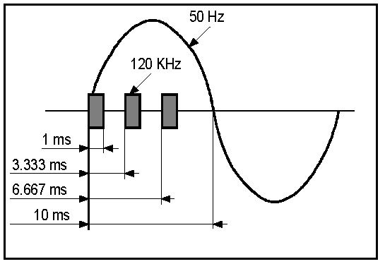 Figure 1
 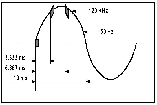 Figure 2
Note. - For clarity, the signals in figure 1 are shown as they would be seen through a high pass filter. The 50Hz. wave form is only shown for reference. In reality the signals are actually superimposed on the 50Hz. wave form and look more like that shown in figure 2.
A complete code transmission encompasses eleven cycles of the power line. The first two cycles represent a Start Code. The next four cycles represent the House Code and the last five cycles represent either a Number Code (1 thru 16) or a Function Code (On, Off etc.). This complete block, (Start Code, House Code, Key Code) should always be transmitted in groups of 2 with 3 power line cycles between each group of 2 codes. Bright and dimare exceptions to this rule and should be transmitted continuously (at least twice) with NO gaps between codes. See figure 3.
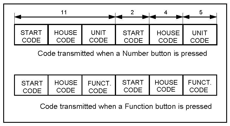 Figure 3
Within each block of data, each four or five bit code should be transmitted in true and complement formon alternate half cycles of the power line. i.e. if a 1 millisecond burst of signal is transmitted on one half cycle, (binary 1) then no signal should be transmitted on the next half cycle, (binary 0). See Figure 4 below.
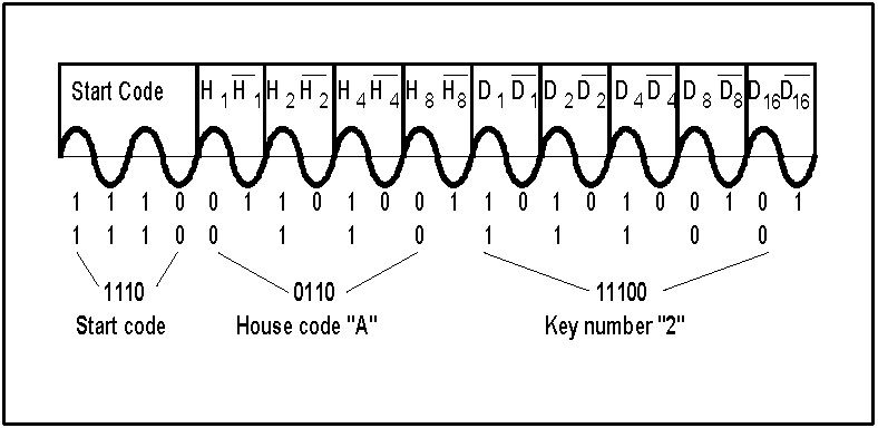 Figure 4
The Tables in figure 5. show the Binary Codes to be transmitted for each House Code and Key Code. The Start Code is always 1110 which is a unique code and is the only code which does not follow the true complement relationship on alternate half cycles.
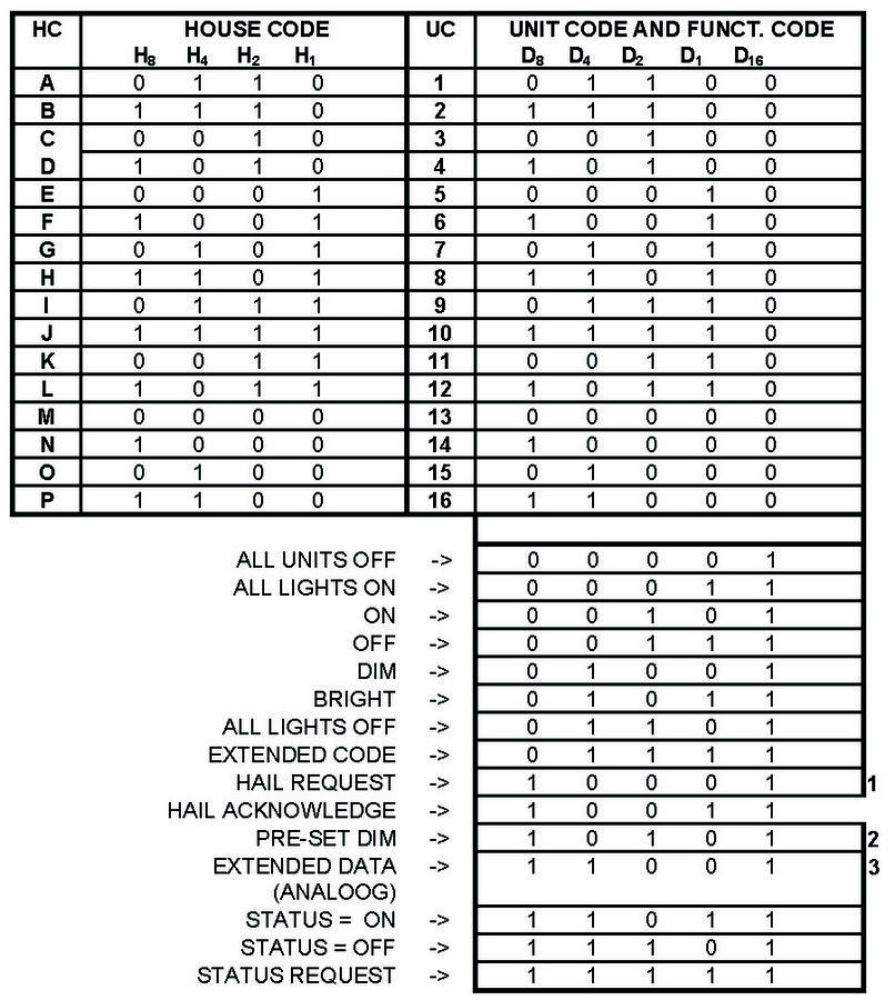
Figure 5. House Code and Key Code Tables.
- Hail Request is transmitted to see if there are any other MARMITEK X-10 PRO transmitters within listening range. This allows the OEM to assign a different Housecode if a "Hail Acknowledge" is received.
- In a Pre-Set Diminstruction, the D8 bit represents the Most Significant Bit of the level and H1, H2, H4 and H8 bits represent the 4 Least Significant bits
- The Extended Data code is followed by 8 bit bytes which can represent Analog Data (after A to D conversion). There should be no gaps between the Extended Data code and the actual data, and no gaps between data bytes. The first 8 bit byte can be used to say how many bytes of data will follow. If gaps are left between data bytes, these codes could be received by Marmitek X-10 Modules causing erroneous operation.
Extended Code is similar to Extended Data: 8 Bit bytes which follow Extended Code (with no gaps) can represent additional codes. This allows the designer to expand beyond the 256 codes currently available
